
This command opens a dialog box that enables the user to view (or modify) the parameters imported from an experimental data file.
 If the Tab-Window: Experiments is empty the active simulation (in the Tab-Window: Simulations) is used as an template for creating a new experiment before starting the import of the data stored in the ASCII-file. Consequently, if the ASCII-file does only contain voltage/current couples, the parameters associated with the experiment (such as parameters referring to Scan, Pre-Equilibrium, Diffusion, Geometry or Experimental Parameters) will be those of the active simulation. Otherwise (i.e. if the Tab-Window: Experiments is not empty) the active experiment will be taken as the template. If the ASCII-file contains additional information (concerning Scan, Pre-Equilibrium, Diffusion, Geometry or Experimental Parameters) the parameters from the template will be overwritten by the imported ones.
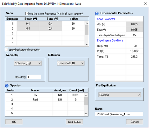
Disabled entries refer to data extracted from the imported curve which should not be modified by the user.
Most of the parameters have the same meaning as already described for cyclic voltammetry. The meaning and functionality of the Scan Parameters is as follows:
Scan Parameters:
•Scan segment, Estart (V), Eend (V), f(Hz)
DigiElch provides a highly flexible way for defining the potential scan used in the square wave experiment. The overall scan can be composed of any number of scan segments characterized by starting potential, Estart (V), end-potential, Eend (V) and the square wave frequency, f (Hz).
•Check Box: use the same value of f(Hz) in each scan segment
If this check box is ticked any modification of f (Hz) will be taken over for all other scan segments.
•Check Box: apply background correction
This check box is visible only if both Ru (Ohm) and Cd (F) are different from zero. The need for this option is similarly as demonstrated in the CV-example.
This check box is visible only if Cdl (F) > 0 and Ru(Ohm) > 0.
•Esw (V), dEs (V)
Square wave amplitude and potential steps. The definition of the square-wave signal by Estart (V) = Ei, Esw (V) , dEs (V) and f(Hz) = τ-1 becomes clear from the following picture:

Figure 1
•Time steps/SW-halfcylce
Indicates the number of time steps used for simulating the current referring to the end points of the t/2 - cycles.
