
This command opens a dialog box that enables the user to view (or modify) the parameters imported from an experimental data file.
 If the Tab-Window: Experiments is empty the active simulation (in the Tab-Window: Simulations) is used as an template for creating a new experiment before starting the import of the data stored in the ASCII-file. Consequently, if the ASCII-file does only contain voltage/current couples, the parameters associated with the experiment (such as parameters referring to Scan, Pre-Equilibrium, Diffusion, Geometry or Experimental Parameters) will be those of the active simulation. Otherwise (i.e. if the Tab-Window: Experiments is not empty) the active experiment will be taken as the template. If the ASCII-file contains additional information (concerning Scan, Pre-Equilibrium, Diffusion, Geometry or Experimental Parameters) the parameters from the template will be overwritten by the imported ones.
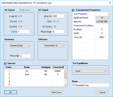
Disabled entries refer to data extracted from the imported curve which should not be modified by the user.
Most of the parameters have the same meaning as described for cyclic voltammetry. The meaning and functionality of the other parameter is as follows:
1. DC - Signal
•Check Box: Single Scan
This check box is activated if only the forward scan of the DC-signal has been executed. Eend (V) is automatically set equal to Erev(V) and the input field for Eend (V) will be blocked.
•Estart (V), Erev (V), Eend (V), v(s)
The DC-scan can be composed of up to 2 scan segments characterized by starting potential, Estart (V), reversing potential, Erev (V), end-potential, Eend (V), and scan rate, v (V/s).
2. Scan Parameters
•log2(Data Points)
The number of data points used for generating the signal. It must be an integer power of 2 and is 2^14 = 16384 by default.
•dEdc (V)
The potential difference between subsequent data points (fitting the selected number of Data Points) is shown in the (read only) parameter dEdc(V).
3. AC - Signal
•dEac (V), f(Hz), Phase Angle
The superimposed AC-signal is characterized by Amplitude, dEac (V), frequency, f(Hz), and Phase Angle. The frequency is adjusted such as to ensure an integer value for the number of AC-Cycles.
Ideally the sum of the AC and DC signal should converge to Estart (V) at t => 0. Consequently, the ideal AC-signal should be a sinus with a Phase Angle of 0. Unfortunately, when conducting FT-CV-Experiments from within DigiElch (having a GAMRY potentiostat connected) it is not possible to synchronize the DC-signal (generated by the potentiostat's DAC-converter) with the AC-signal (generated by the potentiostat's signal-processor). For this reason the Phase Angle actually used in an experiment will randomly vary from experiment to experiment. This is why DigiElch provides the option to enter the phase angle to which a FT-CV-simulation refers (with respect to an ideal sinus signal).
•AC-Cycles
The integer number of AC-Cycles which is superimposed to the DC-signal.
