
This command opens a dialog box that enables the user to view (or modify) the parameters imported from an experimental data file.
 If the Tab-Window: Experiments is empty the active simulation (in the Tab-Window: Simulations) is used as an template for creating a new experiment before starting the import of the data stored in the ASCII-file. Consequently, if the ASCII-file does only contain voltage/current couples, the parameters associated with the experiment (such as parameters referring to DC-Signal, AC-Signal, Pre-Equilibrium, Diffusion, Geometry or Experimental Parameters) will be those of the active simulation. Otherwise (i.e. if the Tab-Window: Experiments is not empty) the active experiment will be taken as the template. If the ASCII-file contains additional information (about DC-Signal, AC-Signal, Pre-Equilibrium, Diffusion, Geometry or Experimental Parameters) the parameters from the template will be overwritten by the imported ones.
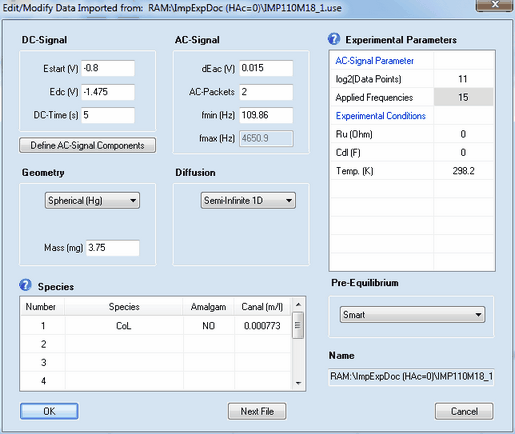
Disabled entries refer to data extracted from the imported curve which should not be modified by the user.
Most of the parameters have exactly the same meaning as already described for cyclic voltammetry. The meaning and functionality of the remaining parameter is as follows:
1. DC - Signal
•The simulation is executed for an experiment conducted in the following way: at the beginning of the experiment the potential of the electrode is at Estart (V) so that the initial concentrations are in agreement with the Pre-Equilibrium condition referring to this potential. Then the electrode potential jumps to Edc (V) and remains at this value for the time indicated by DC-Time (s) before the AC-Signal is superimposed.
2. AC-Signal Parameters
•log2(Data Points)
The number of data points used for generating the AC-signal. It must be an integer power of 2 and is 2^11 = 2048 by default.
•Applied Frequencies
Number of frequency components from which the multi-sine AC-signal is generated.
3. AC - Signal
•dEac (V), AC-Packets, fmin (Hz), fmax (Hz)
The AC-Signal is composed of up to 15 frequencies components. The latter can be edited/defined by clicking on the button Define AC-Signal Components
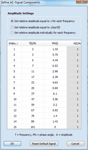
Each component of the AC-signal is defined by frequency, fi, phase angle, φi, and amplitude, Ai. These values are relative values referring to the basic frequency, fo (i.e. the frequency which would be obtained if the signal formed by the 2n data points (where n is the number defined in log2(Data Points)) covers exactly a single sinus cycle.) The overall AC-Signal is generated using the number of frequency components defined in Applied Frequencies. Then the amplitude of the overall signal is adjusted such as to mach the value defined in dEac (V) and the time regime of the simulation is adjusted in such a way that the lowest frequency component is equal to fmin (Hz). The "real world" value of the highest frequency component, fmax (Hz), depends on the number of Applied Frequencies and the value entered for fmin (Hz). The overall AC-Signal is repeatedly applied n-times where n is the number defined in AC-Packets. Consequently, AC-Packets = 2 means that the overall signal is applied twice in the course of the simulation while the Fourier-Transformation is always executed for the last of the applied AC-Packets.
A simulation referring to an IMP-experiment starts with computing the concentration referring to Estart (V) and the selected Pre-Equilibrium condition. In the next step the concentration profiles referring to the potential Edc (V) at the end of DC-Time are simulated. Then the simulation of the concentration profiles is continued taking also the superimposed AC-Signal into consideration. At the end of the simulation the current simulated for the last AC-Packet and the applied electrode potential are analyzed by Fourier transformation. In the last step, the real and imaginary part of the impedance is computed from these data for each frequency component.
