 A value of Cdl (F) written in magenta indicates that a time/potential dependent double layer capacity has been entered by the user. The polynomial coefficients describing the dependence of the double layer capacity as function of the electrode potential can be edited by clicking with the right mouse button while the cursor is localized over the input field associated with Cdl (F). A value of Cdl (F) written in magenta indicates that a time/potential dependent double layer capacity has been entered by the user. The polynomial coefficients describing the dependence of the double layer capacity as function of the electrode potential can be edited by clicking with the right mouse button while the cursor is localized over the input field associated with Cdl (F).
The following parameter groups
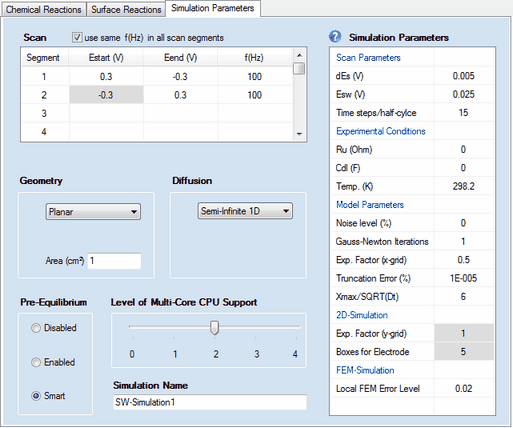
•Geometry •Diffusion •Pre-Equilibrium •Level of Multi-Core CPU Support •Simulation Name
as well as the Simulation Parameters headlined
•Experimental Conditions •Model Parameters •2D-Simulation •FEM-Simulation work exactly in the same way as already described for cyclic voltammetry. The meaning and functionality of the remaining parameters is as follows:
1. Scan Parameters:
•Scan segment, Estart (V), Eend (V), f(Hz)
DigiElch provides a highly flexible definition of the potential scan used in the cyclic voltammetric experiment. The overall scan can be composed of up to 20 scan segments characterized by starting potential, Estart (V), end-potential, Eend (V) and the square wave frequency, f (Hz).
Examples 1: (classical SW-experiment, 1 scan segment is executed)
segment index
|
Estart (V)
|
Eend (V)
|
f (Hz)
|
comment
|
1
|
0
|
-1
|
100
|
Potential moves from 0 to -1V with f=100 Hz
|
| Examples 2: (cyclic SW-experiment, 2 scan segments are executed) |
segment index
|
Estart (V)
|
Eend (V)
|
f (Hz)
|
comment
|
1
|
0
|
-1
|
300
|
forward scan from 0 to -1V with f=300 Hz
|
2
|
-1
|
0
|
300
|
backward scan from -1 to 0V with f=300 Hz
|
Examples 3: (3 scan segments are executed )
segment index
|
Estart (V)
|
Eend (V)
|
f (Hz)
|
comment
|
1
|
0
|
-0.5
|
300
|
forward scan from 0 to -0.5 with f=300 Hz
|
2
|
-0.5
|
-1
|
200
|
forward scan continues to -1V with f=200 Hz
|
3
|
-1
|
1
|
400
|
backward scan from -1V to +1V with f=400 Hz
|
Estart - values plotted on a grey background are automatically filled in. They are "read only" and cannot be edited/modified. This ensures a "smooth scan" where the starting potential of a scan is always equal to the end potential of the previous scan.
•Check Box: use the same value of f(Hz) in each scan segment
Any modification of f (Hz) will be taken over for all other scan segments if this check box is ticked. •Check Box: apply background correction
This checkbox is visible only if both Ru (Ohm) and Cd (F) are different from zero. The need for this option is similarly as demonstrated in the example. •Time steps/segment
Defines how many time steps are executed in each scan segment for covering the time interval entered for time (s) . •Esw (V), dEs (V)
Square wave amplitude and potential steps. The definition of the square-wave signal by Estart (V) = Ei, Esw (V) , dEs (V) and f(Hz) = τ-1 becomes clear from the following picture:
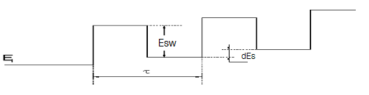 Figure 1
•Time steps/SW-halfcylce
Indicates the number of time steps used for simulating the current referring to the end points of the t/2 - cycles.
Removing scan segments:
A scan segment (and all subsequent scan segments) can be removed by entering an empty string into the associated Eend - input filed. For instance, if a user wants that only the first scan segment is executed in Example 2, an empty string must be entered into the input field "Eend (V)" associated with the scan index 2.
τ (and consequently f(Hz)) must be equal within a scan segment (characterized by starting and end potential) but may differ from scan segment to scan segment. Esw and dEs must be equal in all scan segments.
|

