Ribbon Bar Command: Filter Settings |

|

|
|
Ribbon Bar Command: Filter Settings |
|
|
Ribbon Bar Command: Filter Settings |
|
|
|
Ribbon Bar Command: Filter Settings |
|
|
This command opens a dialog box
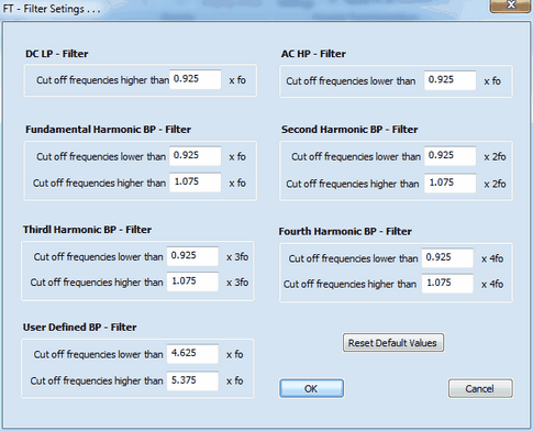
which can be used for customizing the Fourier Transform Filter. The effect of the filter settings for the individual plotting options is as follows:
•Option: Plot AC + DC
The unfiltered total total current is plotted. The filter settings have no effect on the displayed current curve.
•Option: Plot DC
Only the DC-component of the current is plotted. The cut off frequency of the low-pass filter is given by the value computed from fo and the factor entered for the DC LP - Filter where fo is an abbreviation for the frequency, f(Hz), of the AC-Signal.
•Option: Plot AC
Only the AC-component of the current is plotted. The cut off frequency of the high-pass filter is given by the value computed from fo and the factor entered for the AC HP - Filter where fo is an abbreviation for the frequency, f(Hz), of the AC-Signal.
•Option: Plot 1. Harmonic
Only the Fundamental Harmonic current component is plotted. The cut off frequency of the band-pass filter is given by the value computed from fo and the factor entered for the Fundamental Harmonic BP - Filter where fo is an abbreviation for the frequency, f(Hz), of the AC-Signal.
•Option: Plot 2. Harmonic
Only the Second Harmonic current component is plotted. The cut off frequency of the band-pass filter is given by the value computed from fo and the factor entered for the Second Harmonic BP - Filter where fo is an abbreviation for the frequency, f(Hz), of the AC-Signal.
•Option: Plot 3. Harmonic
Only the Third Harmonic current component is plotted. The cut off frequency of the band-pass filter is given by the value computed from fo and the factor entered for the Third Harmonic BP - Filter where fo is an abbreviation for the frequency, f(Hz), of the AC-Signal.
•Option: Plot 4. Harmonic
Only the Fourth Harmonic current component is plotted. The cut off frequency of the band-pass filter is given by the value computed from fo and the factor entered for the Fourth Harmonic BP - Filter where fo is an abbreviation for the frequency, f(Hz), of the AC-Signal.
•Option: User Defined
The Harmonic current component defined by the user is plotted. The cut off frequency of the band-pass filter is given by the value computed from fo and the factor entered for the User Defined BP - Filter where fo is an abbreviation for the frequency, f(Hz), of the AC-Signal.
•Option: Plot 1. Harmonic Envelope
Only the Envelope of the Fundamental Harmonic current component is plotted. The cut off frequency of the band-pass filter is given by the value computed from fo and the factor entered for the Fundamental Harmonic BP - Filter where fo is an abbreviation for the frequency, f(Hz), of the AC-Signal.
•Option: Plot 2. Harmonic Envelope
Only the Envelope of the Second Harmonic current component is plotted. The cut off frequency of the band-pass filter is given by the value computed from fo and the factor entered for the Second Harmonic BP - Filter where fo is an abbreviation for the frequency, f(Hz), of the AC-Signal.
•Option: Plot 3. Harmonic Envelope
Only the Envelope of the Third Harmonic current component is plotted. The cut off frequency of the band-pass filter is given by the value computed from fo and the factor entered for the Third Harmonic BP - Filter where fo is an abbreviation for the frequency, f(Hz), of the AC-Signal.
•Option: Plot 4. Harmonic Envelope
Only the Envelope of the Fourth Harmonic current component is plotted. The cut off frequency of the band-pass filter is given by the value computed from fo and the factor entered for the Fourth Harmonic BP - Filter where fo is an abbreviation for the frequency, f(Hz), of the AC-Signal.
•Option: Plot User Defined Envelope
Only the Envelope of the Harmonic current component defined by the user is plotted. The cut off frequency of the band-pass filter is given by the value computed from fo and the factor entered for the User Defined BP - Filter where fo is an abbreviation for the frequency, f(Hz), of the AC-Signal.
![]() The appearance of the FT-CV-current curve may strongly depend of the filter settings (except for plotting the total unfiltered AC + DC - current). This must be kept in mind when comparing or fitting experimental FT-CVs with those simulated by DigiElch.
The appearance of the FT-CV-current curve may strongly depend of the filter settings (except for plotting the total unfiltered AC + DC - current). This must be kept in mind when comparing or fitting experimental FT-CVs with those simulated by DigiElch.